|
Operation:
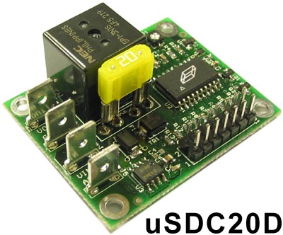
The uSDC or Micro-Shut-Down-Controller is an electronically controlled
automotive power switching device. It is primarily designed for the purpose of
starting up or shutting down a personal computer used in a motor vehicle. It
interfaces with a computer motherboard’s power switch header that would
normally connect to the push-button switch on the front of a personal computer
case. The uSDC includes a high current relay that will cut off or apply all
power to the power supply of the personal computer to prevent any substantial
current draw when the computer is not in use. The uSDC also provides a timing
mechanism that is user selectable allowing the computer to remain “on” for
an amount of time after the ignition has been turned off. The uSDC allows the
user to mount the personal computer in remote locations (such as a trunk) and
provides hands off method automating the startup and shutdown sequence while
constantly monitoring the environmental conditions.
Documentation:
 |
uSDC20D Quick User Guide |
|
uSDC20D Input Power Connection Options |
|
uSDC20D Full Specification |
|
uSDC20D Aux Output Connection Options |
Connection Diagram:
Connection Diagram Explained:
1.
The Yellow VIN connection should be a heavy gauge connection (12 or 10)
gauge wire directly to the battery. This is the line where most of the current
will flow.
2.
The Red ACC (Accessory) line can be light gauge wire. It connects to the
Accessory line. This is the same line that turns on a car stereo only when the
ignition is clicked into the second position.
3.
Red VOUT line connects to the + side of a 12 volt computer power supply
or DC-AC inverter connected to a computer power supply. It should be heavy (12
or 10) gauge wire.
4.
The purple MB Power SW is a 2 pin jumper cable that is connected from the
controller to the motherboards power switch. Make sure the polarity is correct,
if it is backwards it won’t damage anything but it turn on or off the
computer.
5.
The computer Power Sense cable consists of a signal Diode that connects
from the controller to a 4 pin molex computer Hard Drive or CD-Rom Power
connector. This is how the controller detects the computer is on so that is
doesn’t inadvertently turn on/off the computer when it is already on or off.
It also allows Power Down Mode to be very short.
6.
The Optional User Switch is a momentary switch that is pressed to turn
off the computer faster, see the operational timing diagram.
7.
The Thick Black wires are heavy gauge Ground wires. The black wire going
to the controller should be at least 18 gauge or thicker. It doesn’t carry
much current, but is used for voltage sensing.
Specification Table:
|
Quick
Specifications |
uSDC20D |
Notes |
| Dimensions |
1.85"L X
1.5"W X 1"H |
The circuit board is 0.062" thick. |
| Mounting Holes |
4
- 0.125" grounded holes |
Mounting holes are located at
(0.13",0.13"),(0.137",0.13"),(0.13",0.172")
(0.137",0.172") |
| Operating Voltage |
7 - 24 V |
The voltage range at which the unit will
operate, this does not mean that the unit will output 12 volts over this
range. It is a switch/relay device and not a power conversion device. |
| Power Terminals |
0.052"Thick,
0.250"Wide Lug |
Lugs use standard off the
shelf mating connectors (J1-J4) |
| Jumper Block |
2x7,
0.1"Spacing |
(JP1) Used for connecting signals to the motherboard,
configuring options, and external power button. (JP1) |
| Standby Current |
50 uA typical
|
The amount of current the
unit draws when the car is off, and all timers have expired (sleep state)
the smaller, the longer the car can sit without draining the battery. |
| Max Operating Current |
< 80 mA |
The maximum amount of current the shutdown
controller itself will draw when on and functioning |
| Operating Temperature |
-40C to 85C |
The temperature at which the
micro controller will operate and provide protection for the devices
connected to it. (see range below for allowable computer range) |
| Max Load Current |
20 A |
The maximum amount of current the computer can
draw through the switch of the shutdown controller |
| Temperature Protection |
Yes |
The unit will detect if the
ambient is too hot or too cold to function without damage.
Will prevent power-up and initiate shutdown if out of the operating range (0
degrees C to 50 degrees C) |
| Voltage Sense / Protection |
Yes |
Ability to see how much voltage is coming from
the battery, or detect that the car is running to turn on. Prevent over
discharge. |
| Low Voltage Adjust |
Yes |
An adjustable pot is provided
to fine tune the low voltage at which the shutdown controller will attempt
to turn off the down stream device. |
| Over Voltage Protection |
Yes |
If too much voltage is connected to the
shutdown controller, the transient suppressor will dissipate the energy
and cause the fuse to blow |
| Optional Auxiliary Output |
Yes |
Will drive an external relay
or turn on a power supply when operating. Useful for remote power (I.E.
in-dash display) Includes a delay to support no "clicks or pops"
when used as an Audio Amp Enable. |
| Adjustable Delay Time |
Yes |
An adjustable pot is provided to select the
turn off timer (0-30 minutes) |
| Fuse Protection |
Yes |
If the shutdown controller or
a device connected to the shutdown controller draws too much current due
to a fault condition (Load Dump or other), the fuse will blow protecting
downstream devices |
| Reverse Voltage Protection |
Yes |
If the Shutdown controller has it's input
polarity reversed, it will cause the fuse to blow before damaging the unit
and devices connected to it. |
| Optional Power Button |
Yes |
Manual override for the
automatic startup and shutdown of the computer |
| Computer "On" Sensing |
Yes |
Allows the detection of the computer being
shutdown by software so that the timed shutdown pulse, doesn't
inadvertently turn the computer back on when it was suppose to stay off. |
| Ignition/Accessory Line |
Yes |
The unit is controlled by the
accessory line similar to the way the radio is controlled by the keys
turning on the ignition |
| Status LED |
Yes |
An LED to indicate which mode of the timing
sequence the unit is in. Also used for fault conditions |
General Timing Diagram:
Timing Diagram Explanation:
No PWR Mode:
When you first connect power to Vin
of the shutdown controller it will power up into sleep mode. No PWR mode means
that the permanently connected Vin terminal isn’t connected to the battery
yet.
Sleep Mode:
After long periods activity the
controller will go into this mode drawing minimal battery power.
Running Mode:
When the Accessory line goes high
and VOUT gets connected to VIN (and the Relay clicks). The LED comes on solid
and a time (t1) later the power up pulse (MB Power SW) is sent to the
motherboard. At this point the computer turns on and starts booting. The engine
would be started some time during this interval and the devices connected must
be able to survive engine cranking. To exit running mode the Accessory line must
go low. The engine is typically turned off before the Accessory circuit gets
disconnected, but both can turn off simultaneously.
(t1) is 2 seconds by default
Count Down Mode:
In this mode the computer is waiting
for an amount of time (t2) specified by the adjustment at P1. The LED flashes
once per second in this mode. Fully clockwise allows maximum delay time and
fully counter clockwise is minimal delay. Any time during this count down, the
user switch can be pressed forcing the timer to go to zero and starting the
Power Down Mode. If the Accessory signal comes back on during this time, the
controller will go back into the middle of Running Mode not sending any pulses
to the motherboard.
(t2) is adjustable between 0 and 30
minutes.
Power Down Mode:
After the previous timer expires,
the power down pulse is sent to the motherboard (MB Power SW) The controller
then waits for a time (t3) for the computer to shutdown or detects that the
computer has turned off by monitoring the (Computer On) signal. The LED flashes
twice per second in this mode. If the Accessory signal comes back on during this
time the controller will wait for the computer to shut down and start over at
the beginning of Running Mode sending a pulse to the motherboard to start back
up.
(t3) is 90 seconds
Jumper Block Description:
Jumper Options:
User Modes:
0: Default User Mode, explained in the timing diagram. Start up pulse
is sent when ACC goes high.
1: Voltage Sense Start Mode. In this mode the controller will wait
until the car battery voltage is above 13 volts indicating that the engine is
running and the alternator is charging the battery or keeping it charged. This
mode is useful if you have a power supply that requires more than 12 volts to
operate or your worried about the "Engine Cranking Transients." When
the car is turned off (ACC goes low), the controller behaves the same as the
default mode.
2: Temperature Sensor Disable.
3: Enables Temp Sensor Disable and Voltage Sense Start Mode
Ordering:
The Mpegbox uSDC20D is available now!
If you are interested in one
please send email to orders@mpegbox.com
|